Simulation Experiment: Silicon Waveguide #36
Labels
No Label
abstractions
architecture
bug
distribution
docs
duplicate
enhancement
feature
physical
proposal
question
simulation
tooling
tracker
unconfirmed
ux
wontfix
No Milestone
No project
No Assignees
1 Participants
Notifications
Total Time Spent: 4 hours

Due Date
so-rose
4 hours
No due date set.
Blocks
#20 Simulation Experiment: Tracker
so-rose/blender_maxwell
Reference: so-rose/blender_maxwell#36
Loading…
Reference in New Issue
There is no content yet.
Delete Branch "%!s(<nil>)"
Deleting a branch is permanent. Although the deleted branch may exist for a short time before cleaning up, in most cases it CANNOT be undone. Continue?
A benchmarking simulation with the following parameters:
\lambda.\lambdain a gradient-based optimization.Ran simulation with
PointDipoleNodeinstead of a finite-extent plane wave, "get it going" (top next step is implementing an angled finite-extent gaussian plane wave).Managed to get it working quite well w/end-to-end design-run-analysis.
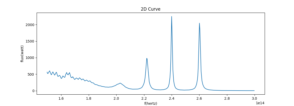
Transmission Curves
The following plots are computed directly in the
.blend, per-\lambdausingF_{\text{inj}}(\lambda) / F_{\text{*}}(\lambda), whereinjrefers toand
*refers to:10um
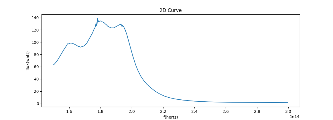
40um
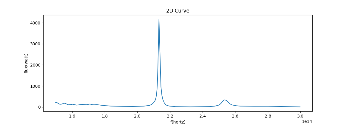
80um
Next Steps
PointDipoleNode, since they should experience a characteristic "leakage" - "leakage" that makes them generally unsuitable for doing this kind of analysis with them. I did manage to get a 3D voxel field of the first and last micrometer (w/space around) out, but with a resolution ofx,y,z,t = 17,3,12,1025, it's quite pointless to look at (though fun playback!)PointDipolereally messes up any hope of useful results (if the idea is to analyze the waveguide's transmission loss. I need a finite-extent angled source, and I'd like to impelement theGaussianBeamto that end.ModeSourcefor automating the process of finding/solving for guided mode resonances, as well as helper utilities to build waveguides, I'd rather focus on understanding the primitives that let me inject EM waves in more flexible ways. The node tools are very good at turning flexibility into usability, and right now I need to be able to say "I need an angled wave".vacwl -> wattgraph, not afreq -> watt. We also will be needing to combine them. On the whole, one is already missing the TODO math nodesTransformandExpand.Bugs
Many bugs were found. None so far are show-stoppers; simply annoyances that I've been doing my very best to document, fix, etc. .
Some are also simply papercuts in terms of UX. Like the lack of unit-dimension-guided socket colors. These kinds of things are equally important to fix - "confusing" is a bug.
Before I continue, I'll be making Issues for what I find and closing them as a way to document my progress.